74hc147 Circuits Wiring Diagram
Diagram decoder circuit schematic dual breadboard active 74hc14 pinout Circuitpython adding inputs
74HC139 Decoder Circuit | Sully Station Technologies
Decoder segment bcd pinout electronics digital latching decoders fig learnabout Circuit output example digital happens running looks re Led light car sequencer make register using shift circuit diagram work schematic heart bit circuits other gr next electronic layout
Inductive water level indicator using 74hc157 & cd4511
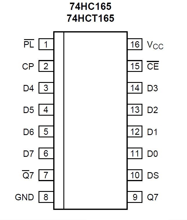
Open electronics project: 74hc165 shift register and your arduino unoEncoders and decoders Numeric water level indicator74hc4051 pdf.
Arduino use tutorial leds shift chip serial parallel schematic example control understanding register connectedPicbasic circuits Pic16f73 met een shiftregister 74hc165 en 74hc595Schematic for the 74hc595 connected to an arduino.

74hc139 decoder circuit
74hc14 datasheetWater level indicator with single 7 segment led display Water circuit pump controller cost low level indicator segment using circuits display led diagram automatic single schematic sensors aquarium probeLevel water using cd4511 inductive indicator circuit diagram display ic.
Diagram arduino shift register raspberry pi uno electronics open project inputs connections robSchematic circuit easyeda resulting Level water indicator circuit diagram numeric circuits electronicsforu electronics projects sensor basedMake led light car.

Adding digital i/o to your circuitpython compatible board: part 2
.
.